The Rev Dodgson said:
Spiny Norman said:
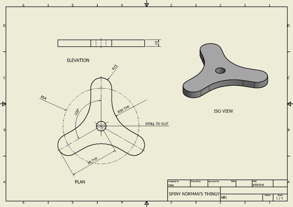
One for the people good at calculating geometric shapes and the like.
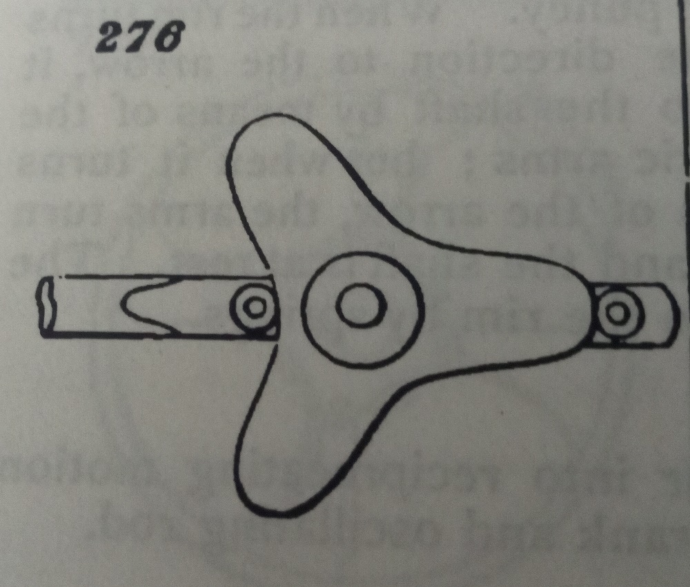
I’d like to know the process of how to generate the tri-lobe shape in the picture below. As it spins, the roller bearings on either side move left/right. And by having roller bearings the contact points moves around because the varying ramps on the tri-lobe shape will also move around on the bearings. The difference in the upper and lower radii of the lobes is going to be 69 mm.
Is there some software that I could use?
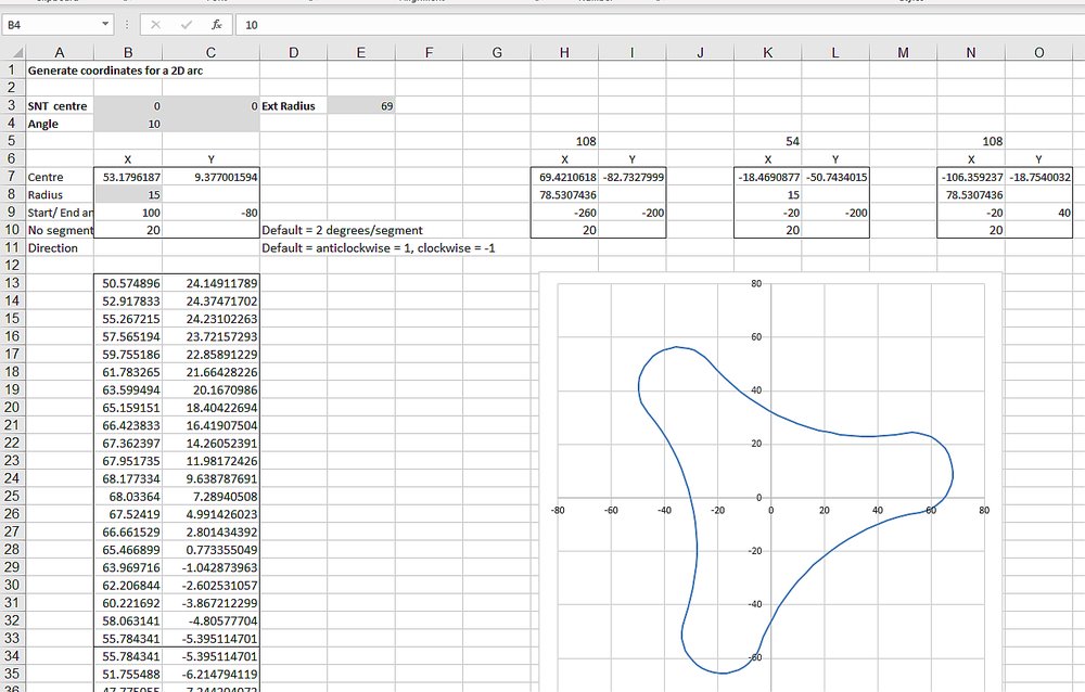
Heard of Excel? :)
There’s probably other stuff that would make it easier though. It looks like there is a variable radius in between the curves, so you’d need more details to get exact coordinates.
Ta to PWM & Rev.
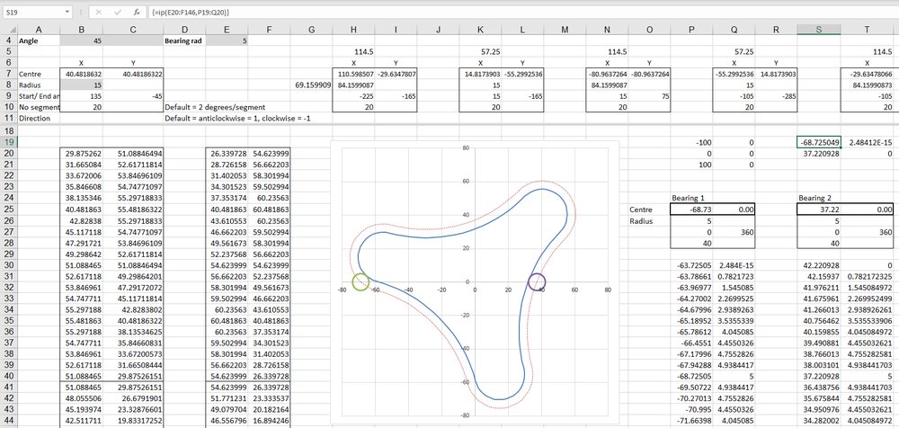
I can easily draw a shape like that, but the question is not that simple – The shape needs to just touch the two roller bearings all the time as the tri-lobe section spins around. I could do it easily enough (maybe …) if it were just two points that were touching the lobes, but for what I want to use it for I have to use roller bearings and so the contact point between the bearings and the lobes will vary, depending upon the angle of slope of the lobes and the diameter of the bearings.
I could come up with something close by rotating a rough drawing (in CAD) around in something like 5° to 10° increments, but there must be a simpler and more accurate way to do it.