The calculations are now all “on-sheet”
The procedure is:
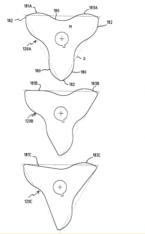
1. Enter lobe height and radius and angle of first lobe to X axis.
2. Find coordinates of centres of each lobe
3. Generate 180 degree arc for each lobe.
4. Find centres of each inter-lobe arc (the intersection of a radius line through the end of one arc and the start of the next one.
5. Find radius of inter-lobe arcs (should all be the same).
6. Generate 60 degree arc between each lobe.
For the valve locations, they are not actually a constant distance apart. You find the X coordinate of the two points where the trilobe line crosses the X axis. The valve centre is then 5 (or whatever the radius is) to the left or right of each point.
To see the formulas for any point, place the cursor on the cell and press F2, all the cells referenced by the formula will be highlighted (if they are on the screen).
HTH