Date: 16/02/2020 16:58:32
From: Woodie
ID: 1501276
Subject: LDRs and LEDs
Probably one for Mr Beeny Boy.
LDR = Light Dependant Resistor
LED = Light Emitting Diode
Do LED lights work differently in the working of an LDR than incandescent light?
I know LEDs strobe. Quicker than the human eye can detect.
However, does this “strobing” send an LDR berserk? Are LDRs that responsive that their resistance will go up/down in line with the strobing?
It’s all about the TOOTs. you see. I made this signalling system that works a beaut. (Using Picaxe processors). LDR in the middle of the track. Train goes over, ambient light goes dark. Picaxe code detects the change in resistance of the LDR and turns signal red. Train goes past, and light level resumes, wait 45 seconds and turn signal green. That’s the gist of it, but a little more complex than that.
I’ve replace the incandescent (halogen floodlights) in the train room with LED floodlights.
In short, the signals go berserk. They appear to have no idea what’s going on when under the LED lights.
Any thoughts? Google is not being very helpful.
Date: 16/02/2020 17:19:25
From: SCIENCE
ID: 1501289
Subject: re: LDRs and LEDs
haven’t done the experiments, note many LED are narrow spectrum though
Date: 16/02/2020 22:55:09
From: mollwollfumble
ID: 1501405
Subject: re: LDRs and LEDs
SCIENCE said:
haven’t done the experiments, note many LED are narrow spectrum though
Haven’t done the experiments either, but light sensitive cells (I assume LDRs) are very often used with LEDs. You see them across doorways for instance, and also (unless I’ve heard wrongly) TV remotes.
Have you considered putting a capacitor in parallel with the LDR to filter out any high frequency components that could be affecting the signal?
Date: 16/02/2020 23:17:04
From: sibeen
ID: 1501416
Subject: re: LDRs and LEDs
Woodie, I don’t think I’ve ever used an LDR in my life, and certainly have no understanding of their underlying characteristics, response time, frequency dependencies etc. I hadn’t even thought about LED lights flickering and wasn’t aware that they do. Molly’s idea of a capacitor may have some merit and you may have to look into a schmitt trigger type OP amp to overcome the oscillation and give some decent hysteresis to the circuit. ‘‘btm, you’re the electronics bloke around here, your two cents?
Date: 16/02/2020 23:34:22
From: Woodie
ID: 1501420
Subject: re: LDRs and LEDs
Mr Been,
You can test the value of the LDR resistance in the Picaxe processor. You set the values to be either 0 – 64, or to 128 or 256.
Brighter the light, the less resistance. . On startup, I sample the value, and that value becomes the ambient light. I sample the value 4 times a second, and if the value drops to below 50% of the ambient light, (a train has gone over the LDR) then set the signal to red. etc etc etc. All the signals are linked, so the system passes the current signal’s status (red/yellow/green) to the previous signal. ie. Current signal = red, previous signal will be yellow and so on down the line.
Works fine in ambient room light (coming in through the doors/windows etc, or the old halogen filament lights). Turn the LED floodlights on, and Arthur’s your Martha. It all don’t know where it’s at and all the signal do a fabulous light show.Turn off the LED floodlights and all is fine again. The only thing I can think of is the LED lights “strobing”, and the LDRs are that sensitive that they’re picking up the light/dark 50 times a seconds. I can’t test the LDRs for this. Only have an analogue (needle) multimeter, and I don’t think a digital mutlimeter would pick it up either.
Oh… and if you want to see an LED strobe, just look at one in the dark, and roll you eyes round widely and quickly. Try it with some car red tail lights that are LED.
The LED floodlights are each a block of 50 LEDs. (10 * 5) and I’ve put 5 of them up so far.
Date: 16/02/2020 23:35:45
From: btm
ID: 1501421
Subject: re: LDRs and LEDs
sibeen said:
Woodie, I don’t think I’ve ever used an LDR in my life, and certainly have no understanding of their underlying characteristics, response time, frequency dependencies etc. I hadn’t even thought about LED lights flickering and wasn’t aware that they do. Molly’s idea of a capacitor may have some merit and you may have to look into a schmitt trigger type OP amp to overcome the oscillation and give some decent hysteresis to the circuit. ‘‘btm, you’re the electronics bloke around here, your two cents?
What kind of LDR are you using, Woodie? Are you sure it’s not a phototransistor or photodiode? How are the LED lights connected (DC or AC?) If they’re incandescent replacements from a lighting shop, there’s a switchmode power supply built into the light case, so it’s running on DC, in which case it doesn’t strobe or flicker. What colour are they? Can you be a bit more descriptive with the light sensor’s response than “go berserk”? Or is it the traffic signals that go berserk, so that the picaxe itself that seems to be confused? Are the LDRs connected to opamps at all? How big are the LDRs (eg ORP-12?) Could the LED floodlights be reflected onto the tracks through the train’s wheels, giving successive bright-dark (low-high resistance) bursts, thus confusing the picaxe? Are you able to connect an oscilloscope to the circuit to see what’s happening?
Date: 16/02/2020 23:36:32
From: transition
ID: 1501422
Subject: re: LDRs and LEDs
quick read, you’ll need some capacitance in your light sensor circuit (assuming it works with that spectrum of light okay) to take out the LED flicker maybe
if you post an image of the LDR with whatever resistors (or circuit diagram) etc around it and existing capacitors(if any) I might be be able to consult my genius neuron and help
Date: 16/02/2020 23:38:35
From: sibeen
ID: 1501424
Subject: re: LDRs and LEDs
I was scratching my head a bit about the strobing, btw, If fed via a smps than it’s either the worst smps ever built or something else that I’m not aware about is going on.
Date: 16/02/2020 23:40:19
From: Rule 303
ID: 1501425
Subject: re: LDRs and LEDs
Change back to incandescent lights.
Date: 16/02/2020 23:40:36
From: btm
ID: 1501426
Subject: re: LDRs and LEDs
sibeen said:
I was scratching my head a bit about the strobing, btw, If fed via a smps than it’s either the worst smps ever built or something else that I’m not aware about is going on.
It’s possible they’re using PWM to control brightness or heat. Woodie’s last post says they’re strips of LEDs, so PWM seems more likely.
Date: 16/02/2020 23:41:49
From: sibeen
ID: 1501427
Subject: re: LDRs and LEDs
btm said:
sibeen said:
I was scratching my head a bit about the strobing, btw, If fed via a smps than it’s either the worst smps ever built or something else that I’m not aware about is going on.
It’s possible they’re using PWM to control brightness or heat. Woodie’s last post says they’re strips of LEDs, so PWM seems more likely.
Ah, good call.
Date: 16/02/2020 23:43:54
From: Woodie
ID: 1501428
Subject: re: LDRs and LEDs
btm said:
sibeen said:
Woodie, I don’t think I’ve ever used an LDR in my life, and certainly have no understanding of their underlying characteristics, response time, frequency dependencies etc. I hadn’t even thought about LED lights flickering and wasn’t aware that they do. Molly’s idea of a capacitor may have some merit and you may have to look into a schmitt trigger type OP amp to overcome the oscillation and give some decent hysteresis to the circuit. ‘‘btm, you’re the electronics bloke around here, your two cents?
What kind of LDR are you using, Woodie? Are you sure it’s not a phototransistor or photodiode? How are the LED lights connected (DC or AC?) If they’re incandescent replacements from a lighting shop, there’s a switchmode power supply built into the light case, so it’s running on DC, in which case it doesn’t strobe or flicker. What colour are they? Can you be a bit more descriptive with the light sensor’s response than “go berserk”? Or is it the traffic signals that go berserk, so that the picaxe itself that seems to be confused? Are the LDRs connected to opamps at all? How big are the LDRs (eg ORP-12?) Could the LED floodlights be reflected onto the tracks through the train’s wheels, giving successive bright-dark (low-high resistance) bursts, thus confusing the picaxe? Are you able to connect an oscilloscope to the circuit to see what’s happening?
Mr BTM.
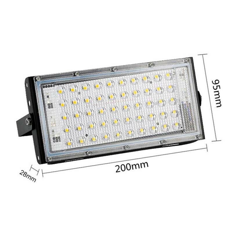
The LED floodlights are these. They are 110 – 220 V AC. What electronics are inside them, I do not know.
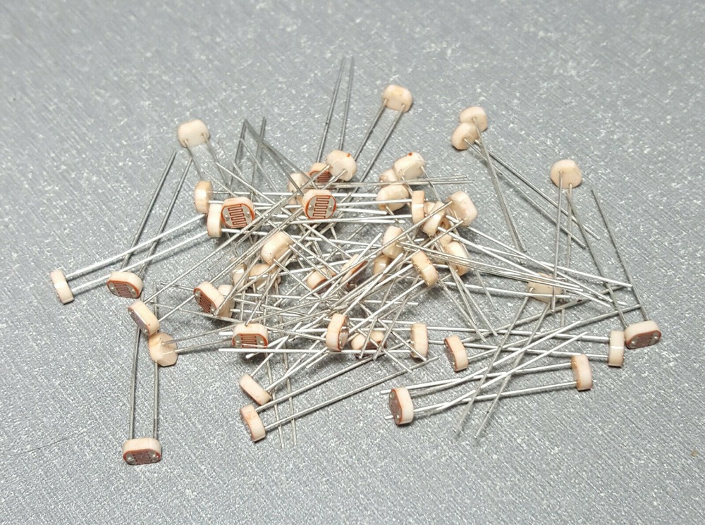
The LDRs (what I call them) are these.
I haven’t programmed the Picaxe for a while. (quite a few years since I designed the whole thing). But I may recall that not only can you set the “value” to sample (0 – 62, 129, 256) there was a setting (for the LDR pins) where you could set the “sensitivity” as well.
Date: 16/02/2020 23:44:19
From: ChrispenEvan
ID: 1501429
Subject: re: LDRs and LEDs
aren’t those strip LED floods just LEDS and resistors and rely on the number of LEDs to get the correct voltage?
Date: 16/02/2020 23:45:20
From: Woodie
ID: 1501431
Subject: re: LDRs and LEDs
transition said:
quick read, you’ll need some capacitance in your light sensor circuit (assuming it works with that spectrum of light okay) to take out the LED flicker maybe
if you post an image of the LDR with whatever resistors (or circuit diagram) etc around it and existing capacitors(if any) I might be be able to consult my genius neuron and help
There are no capacitors in line with the LDRs.
Date: 16/02/2020 23:47:52
From: Woodie
ID: 1501433
Subject: re: LDRs and LEDs
sibeen said:
I was scratching my head a bit about the strobing, btw, If fed via a smps than it’s either the worst smps ever built or something else that I’m not aware about is going on.
I did the “rolling eyes” test on the LED floodlights, and they do “strobe”.
If I swap the AC feed wires around, would they strobe “opposite” to the standard wiring? ie. Swap active/neutral of the AC feed.
Date: 16/02/2020 23:48:59
From: sibeen
ID: 1501434
Subject: re: LDRs and LEDs
Woodie said:
sibeen said:
I was scratching my head a bit about the strobing, btw, If fed via a smps than it’s either the worst smps ever built or something else that I’m not aware about is going on.
I did the “rolling eyes” test on the LED floodlights, and they do “strobe”.
If I swap the AC feed wires around, would they strobe “opposite” to the standard wiring? ie. Swap active/neutral of the AC feed.
No.
Date: 16/02/2020 23:49:21
From: Woodie
ID: 1501435
Subject: re: LDRs and LEDs
Rule 303 said:
Change back to incandescent lights.
The halogen filament globes keep blowing (those long thin ones). Plus they’re 500 W each, and I have 5 of them. The LED floodlights are 50 W each.
Date: 16/02/2020 23:50:26
From: Woodie
ID: 1501436
Subject: re: LDRs and LEDs
btm said:
sibeen said:
I was scratching my head a bit about the strobing, btw, If fed via a smps than it’s either the worst smps ever built or something else that I’m not aware about is going on.
It’s possible they’re using PWM to control brightness or heat. Woodie’s last post says they’re strips of LEDs, so PWM seems more likely.
They aren’t strips. Refer previous pic. You cannot control the brightness of the LED floodlights.
Date: 16/02/2020 23:53:56
From: sibeen
ID: 1501438
Subject: re: LDRs and LEDs
Woodie said:
btm said:
sibeen said:
I was scratching my head a bit about the strobing, btw, If fed via a smps than it’s either the worst smps ever built or something else that I’m not aware about is going on.
It’s possible they’re using PWM to control brightness or heat. Woodie’s last post says they’re strips of LEDs, so PWM seems more likely.
They aren’t strips. Refer previous pic. You cannot control the brightness of the LED floodlights.
OK, that’s PWM off the table.
Date: 16/02/2020 23:57:19
From: Woodie
ID: 1501441
Subject: re: LDRs and LEDs
sibeen said:
Woodie said:
btm said:
It’s possible they’re using PWM to control brightness or heat. Woodie’s last post says they’re strips of LEDs, so PWM seems more likely.
They aren’t strips. Refer previous pic. You cannot control the brightness of the LED floodlights.
OK, that’s PWM off the table.
He’s been off the table for years. :) hehehehehe
Oh… BTW, I know what PWM is. The train loco motor’s electronics use it to vary their speed.
Date: 16/02/2020 23:58:14
From: ChrispenEvan
ID: 1501443
Subject: re: LDRs and LEDs
Woodie said:
btm said:
sibeen said:
Woodie, I don’t think I’ve ever used an LDR in my life, and certainly have no understanding of their underlying characteristics, response time, frequency dependencies etc. I hadn’t even thought about LED lights flickering and wasn’t aware that they do. Molly’s idea of a capacitor may have some merit and you may have to look into a schmitt trigger type OP amp to overcome the oscillation and give some decent hysteresis to the circuit. ‘‘btm, you’re the electronics bloke around here, your two cents?
What kind of LDR are you using, Woodie? Are you sure it’s not a phototransistor or photodiode? How are the LED lights connected (DC or AC?) If they’re incandescent replacements from a lighting shop, there’s a switchmode power supply built into the light case, so it’s running on DC, in which case it doesn’t strobe or flicker. What colour are they? Can you be a bit more descriptive with the light sensor’s response than “go berserk”? Or is it the traffic signals that go berserk, so that the picaxe itself that seems to be confused? Are the LDRs connected to opamps at all? How big are the LDRs (eg ORP-12?) Could the LED floodlights be reflected onto the tracks through the train’s wheels, giving successive bright-dark (low-high resistance) bursts, thus confusing the picaxe? Are you able to connect an oscilloscope to the circuit to see what’s happening?
Mr BTM.
The LED floodlights are these. They are 110 – 220 V AC. What electronics are inside them, I do not know.
The LDRs (what I call them) are these.
I haven’t programmed the Picaxe for a while. (quite a few years since I designed the whole thing). But I may recall that not only can you set the “value” to sample (0 – 62, 129, 256) there was a setting (for the LDR pins) where you could set the “sensitivity” as well.
you sure of those voltages?
I see this one is 220-240v
https://www.gearbest.com/led-flood-lights/pp_3008391572655437.html
Date: 17/02/2020 00:04:58
From: Woodie
ID: 1501445
Subject: re: LDRs and LEDs
ChrispenEvan said:
Woodie said:
btm said:
What kind of LDR are you using, Woodie? Are you sure it’s not a phototransistor or photodiode? How are the LED lights connected (DC or AC?) If they’re incandescent replacements from a lighting shop, there’s a switchmode power supply built into the light case, so it’s running on DC, in which case it doesn’t strobe or flicker. What colour are they? Can you be a bit more descriptive with the light sensor’s response than “go berserk”? Or is it the traffic signals that go berserk, so that the picaxe itself that seems to be confused? Are the LDRs connected to opamps at all? How big are the LDRs (eg ORP-12?) Could the LED floodlights be reflected onto the tracks through the train’s wheels, giving successive bright-dark (low-high resistance) bursts, thus confusing the picaxe? Are you able to connect an oscilloscope to the circuit to see what’s happening?
Mr BTM.
The LED floodlights are these. They are 110 – 220 V AC. What electronics are inside them, I do not know.
The LDRs (what I call them) are these.
I haven’t programmed the Picaxe for a while. (quite a few years since I designed the whole thing). But I may recall that not only can you set the “value” to sample (0 – 62, 129, 256) there was a setting (for the LDR pins) where you could set the “sensitivity” as well.
you sure of those voltages?
I see this one is 220-240v
https://www.gearbest.com/led-flood-lights/pp_3008391572655437.html
These are the actual ones I got off Ebay.
here
It says “AC175 – 265V” on the box and the label on them.
Date: 17/02/2020 00:09:07
From: transition
ID: 1501447
Subject: re: LDRs and LEDs
Woodie said:
transition said:
quick read, you’ll need some capacitance in your light sensor circuit (assuming it works with that spectrum of light okay) to take out the LED flicker maybe
if you post an image of the LDR with whatever resistors (or circuit diagram) etc around it and existing capacitors(if any) I might be be able to consult my genius neuron and help
There are no capacitors in line with the LDRs.
without going back and reading properly
it could be as dumb as needing just a capacitor tied in, i’ve given you a pink one, my favorite color
or may need a resistor as well
if the light level is too low because of the band (LED spectrum of light/sensitivity of LDR), you may need to do more

Date: 17/02/2020 00:09:32
From: ChrispenEvan
ID: 1501448
Subject: re: LDRs and LEDs
Woodie said:
ChrispenEvan said:
Woodie said:
Mr BTM.
The LED floodlights are these. They are 110 – 220 V AC. What electronics are inside them, I do not know.
The LDRs (what I call them) are these.
I haven’t programmed the Picaxe for a while. (quite a few years since I designed the whole thing). But I may recall that not only can you set the “value” to sample (0 – 62, 129, 256) there was a setting (for the LDR pins) where you could set the “sensitivity” as well.
you sure of those voltages?
I see this one is 220-240v
https://www.gearbest.com/led-flood-lights/pp_3008391572655437.html
These are the actual ones I got off Ebay.
here
It says “AC175 – 265V” on the box and the label on them.
says 220V in the specs.
Date: 17/02/2020 00:13:33
From: Woodie
ID: 1501450
Subject: re: LDRs and LEDs
ChrispenEvan said:
Woodie said:
ChrispenEvan said:
you sure of those voltages?
I see this one is 220-240v
https://www.gearbest.com/led-flood-lights/pp_3008391572655437.html
These are the actual ones I got off Ebay.
here
It says “AC175 – 265V” on the box and the label on them.
says 220V in the specs.
Which is what I’ve wired them into anyway.
Date: 17/02/2020 00:18:43
From: Woodie
ID: 1501452
Subject: re: LDRs and LEDs
transition said:
Woodie said:
transition said:
quick read, you’ll need some capacitance in your light sensor circuit (assuming it works with that spectrum of light okay) to take out the LED flicker maybe
if you post an image of the LDR with whatever resistors (or circuit diagram) etc around it and existing capacitors(if any) I might be be able to consult my genius neuron and help
There are no capacitors in line with the LDRs.
without going back and reading properly
it could be as dumb as needing just a capacitor tied in, i’ve given you a pink one, my favorite color
or may need a resistor as well
if the light level is too low because of the band (LED spectrum of light/sensitivity of LDR), you may need to do more
If the light spectrum of the LED floodlights is very narrow, too narrow for the LDR, then the LDRs wouldn’t work at all, would they? ie. They’d think it was dark, and that’s that.
Date: 17/02/2020 00:24:00
From: transition
ID: 1501455
Subject: re: LDRs and LEDs
Woodie said:
transition said:
Woodie said:
There are no capacitors in line with the LDRs.
without going back and reading properly
it could be as dumb as needing just a capacitor tied in, i’ve given you a pink one, my favorite color
or may need a resistor as well
if the light level is too low because of the band (LED spectrum of light/sensitivity of LDR), you may need to do more
If the light spectrum of the LED floodlights is very narrow, too narrow for the LDR, then the LDRs wouldn’t work at all, would they? ie. They’d think it was dark, and that’s that.
depends if it’s running on some threshold, crossing it
but just guessing LDRs have quite a fast response time, you’ve added a noisy light, so you need give the LDR some persistence like your eyes have got, easiest way to do that is to add a capacitor, probably straight across the LDR may do it, depending on current going through it and how firm or soft the supply is to it
Date: 17/02/2020 00:24:29
From: Woodie
ID: 1501456
Subject: re: LDRs and LEDs
Google hasn’t been much help. All it tells me is how to use an LDR to turn an LED on/off using Arduino or Picaxe. Can’t find anything about USING LED lights with an LDR. Much appreciated if anyone can find out, via their channels or point me in a direction where I can find out.
Nie nies.
Date: 17/02/2020 00:27:27
From: Woodie
ID: 1501458
Subject: re: LDRs and LEDs
transition said:
depends if it’s running on some threshold, crossing it
but just guessing LDRs have quite a fast response time, you’ve added a noisy light, so you need give the LDR some persistence like your eyes have got, easiest way to do that is to add a capacitor, probably straight across the LDR may do it, depending on current going through it and how firm or soft the supply is to it
Exactly Mr Sition. And I cannot find out what the LDR response time is. And yes, a “strobing” LED would be a very “noisy” light as you put it.
Date: 17/02/2020 00:31:42
From: Woodie
ID: 1501463
Subject: re: LDRs and LEDs
“Response time of 2 – 50 ms. (Much slower than photo-transistors.)”
Oh dear. I’m nackered if that is the case.
http://lednique.com/opto-isolators-2/light-dependent-resistor-ldr/
I wonder how fast the Picaxe is when it’s sampling the LDR resistance.
Date: 23/02/2020 11:09:53
From: wookiemeister
ID: 1504274
Subject: re: LDRs and LEDs
sibeen said:
Woodie said:
btm said:
It’s possible they’re using PWM to control brightness or heat. Woodie’s last post says they’re strips of LEDs, so PWM seems more likely.
They aren’t strips. Refer previous pic. You cannot control the brightness of the LED floodlights.
OK, that’s PWM off the table.
led light sources without brightness control might well just use a preset
PWM – it has a preset light source that uses
PWM so it doesn’t burn out the
LED
Date: 23/02/2020 11:15:53
From: wookiemeister
ID: 1504276
Subject: re: LDRs and LEDs
your picaxe / microcontroller input might very very function much better if its input is grounded via a 10Kohm resistor.
what happens is that without grounding you get spurious voltages happening caused by static or similar
input pins to things like microcontrollers need to be grounded via a 10Kohm so that the digital input or analog signal is either 1 or 0
1 : use an arduino – picaxe is defunct and problem laden technology
2 grounding the input to the LDR input with a 10kOHM resistor will create a much cleaner and reliable voltage on the input pin
i’ve discovered that even going near a free hanging input pin with plastic clothing will provoke a change at an input pin because the static from the clothing will cause a change at the pin
Date: 23/02/2020 12:09:19
From: transition
ID: 1504288
Subject: re: LDRs and LEDs
wookiemeister said:
your picaxe / microcontroller input might very very function much better if its input is grounded via a 10Kohm resistor.
what happens is that without grounding you get spurious voltages happening caused by static or similar
input pins to things like microcontrollers need to be grounded via a 10Kohm so that the digital input or analog signal is either 1 or 0
1 : use an arduino – picaxe is defunct and problem laden technology
2 grounding the input to the LDR input with a 10kOHM resistor will create a much cleaner and reliable voltage on the input pin
i’ve discovered that even going near a free hanging input pin with plastic clothing will provoke a change at an input pin because the static from the clothing will cause a change at the pin
yeah cmos inputs may need a dampener, pulling up or down, whatever, keep it where meant to be against noise on the line, and any length is like an antenna
Date: 23/02/2020 12:47:19
From: Woodie
ID: 1504301
Subject: re: LDRs and LEDs
wookiemeister said:
your picaxe / microcontroller input might very very function much better if its input is grounded via a 10Kohm resistor.
what happens is that without grounding you get spurious voltages happening caused by static or similar
input pins to things like microcontrollers need to be grounded via a 10Kohm so that the digital input or analog signal is either 1 or 0
1 : use an arduino – picaxe is defunct and problem laden technology
2 grounding the input to the LDR input with a 10kOHM resistor will create a much cleaner and reliable voltage on the input pin
i’ve discovered that even going near a free hanging input pin with plastic clothing will provoke a change at an input pin because the static from the clothing will cause a change at the pin
Each input pin is grounded using a resistor, as the specs say to do. This ensure the pin is “pulled to ground” and works correctly when activated.
Date: 23/02/2020 12:56:57
From: Woodie
ID: 1504311
Subject: re: LDRs and LEDs
Mr Meister and Mr Sition,
You need to remember the circuitry works perfectly, and has done for years under any source of light other than these LED lights. (See above). Even low light levels. I calibrate the system, by taking the ambient light value on the LDR pin and set that as “ambient light”. When that value drops to 50% of the “ambient” light, that means a train has passed over the LDR. This allows the system to work in varying light levels. If I picked a fixed light level to determine if a train has passed over, a low level of ambient light might already be below that level. This allows teh sytem to work with just a 60W incandescent globe in the room (simlulates late evening), or high levels of daylight/floodlight.
What I need to do (I think) is “smooth” out the current being passed through the LDR, which from what I can find, has a very quick response rate to light. Causing the value on the LDR pin to vary widely and rapidly.
Date: 10/04/2022 15:54:37
From: Ian
ID: 1871208
Subject: re: LDRs and LEDs
I have a question which sort of belongs in this thread…
I’m trying to get an old Lego train set working but the 10V AC transformer is cactus. The controller is marked 9V AC. Apparently it’s circuitry converts the input to DC.
Should I be fine to use a12V DC transformer?
Date: 10/04/2022 16:04:11
From: sibeen
ID: 1871209
Subject: re: LDRs and LEDs
Ian said:
I have a question which sort of belongs in this thread…
I’m trying to get an old Lego train set working but the 10V AC transformer is cactus. The controller is marked 9V AC. Apparently it’s circuitry converts the input to DC.
Should I be fine to use a12V DC transformer?
No, no, no, not without knowing quite a bit more. Does the controller have a transformer at its input? If it is just a bridge rectifier at the input, without a transformer, then it will probably be OK. If there is a transformer definitely don’t do it.
Date: 10/04/2022 16:13:37
From: Ian
ID: 1871211
Subject: re: LDRs and LEDs
Date: 10/04/2022 16:18:12
From: sibeen
ID: 1871212
Subject: re: LDRs and LEDs
Ian said:
https://bricks.stackexchange.com/questions/2898/what-is-the-correct-input-voltage-for-the-9v-lego-train-speed-regulator
This describes a very similar controller.. see a few posts down
OK, you should be good. There’s no transformer so the controller can take an AC or DC input.
Date: 10/04/2022 16:23:26
From: Ian
ID: 1871213
Subject: re: LDRs and LEDs
sibeen said:
Ian said:
https://bricks.stackexchange.com/questions/2898/what-is-the-correct-input-voltage-for-the-9v-lego-train-speed-regulator
This describes a very similar controller.. see a few posts down
OK, you should be good. There’s no transformer so the controller can take an AC or DC input.
Yeah, that’s how I figured. Cheers