Date: 22/02/2021 14:06:14
From: mollwollfumble
ID: 1700493
Subject: Compression truss
Question for Rev D.
I have a pin-ended long compression member.
What’s the ideal truss shape?
Question for Rev D.
I have a pin-ended long compression member.
What’s the ideal truss shape?
mollwollfumble said:
Question for Rev D.I have a pin-ended long compression member.
What’s the ideal truss shape?
I’d thought you’d done your own research on that :)
I don’t do steel design, so I don’t really know, but if “ideal” means minimum cost for a given load, using readily available materials, I’d guess a triangular cross section.
I’m 100% sure what your description is, but I imagine you’d be needing something like a conventional roof-truss type structure.
The Rev Dodgson said:
mollwollfumble said:
Question for Rev D.I have a pin-ended long compression member.
What’s the ideal truss shape?
I’d thought you’d done your own research on that :)
I don’t do steel design, so I don’t really know, but if “ideal” means minimum cost for a given load, using readily available materials, I’d guess a triangular cross section.
Well spotted. I did work on an ideal single compression member. It turned out to resemble the double-walled honeycomb-filled tube of an airplane fuselage.
With trusses all I came up with was a truss with 16 longitudinal tubular members in four sets of four in a square layout. Startlingly like the base of the Eiffel Tower, but I have not the slightest idea whether that’s the best possible or not. Nor whether the compression truss should taper towards the ends.
‘Triangular’ is a big hint. Now if only I had some software to try out alternatives.
I’m defining ‘ideal’ here as minimum weight for a given load, rather than cost.
Cost is a more subtle concept that includes optimising joint design and constructability, which I don’t want to go into as a first stage.
Ditto ignoring construction tolerances and assuming linear material elasticity.
The Rev Dodgson said:
mollwollfumble said:
Question for Rev D.I have a pin-ended long compression member.
What’s the ideal truss shape?
I’d thought you’d done your own research on that :)
I don’t do steel design, so I don’t really know, but if “ideal” means minimum cost for a given load, using readily available materials, I’d guess a triangular cross section.
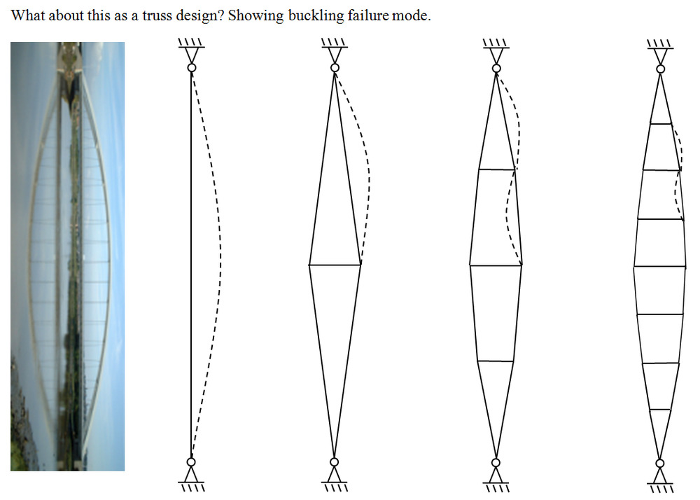
What about this truss design? Side view. In vertical compression only.
It would work like a suspension bridge, but with the main cables in compression rather than tension. The stringers are still in tension.

mollwollfumble said:
The Rev Dodgson said:
mollwollfumble said:
Question for Rev D.I have a pin-ended long compression member.
What’s the ideal truss shape?
I’d thought you’d done your own research on that :)
I don’t do steel design, so I don’t really know, but if “ideal” means minimum cost for a given load, using readily available materials, I’d guess a triangular cross section.
What about this truss design? Side view. In vertical compression only.
It would work like a suspension bridge, but with the main cables in compression rather than tension. The stringers are still in tension.
I don’t think cables work in compression.
Rule 303 said:
I don’t think cables work in compression.
Yes, you very quickly learn that rope isn’t much good at propping up things.
captain_spalding said:
Rule 303 said:I don’t think cables work in compression.
Yes, you very quickly learn that rope isn’t much good at propping up things.
They work better at suspendiing things.
roughbarked said:
captain_spalding said:
Rule 303 said:I don’t think cables work in compression.
Yes, you very quickly learn that rope isn’t much good at propping up things.
They work better at suspendiing things.
(makes note in book)
Rule 303 said:
I don’t think cables work in compression.
True, but with clever placement, they give the illusion that they can. I love tensegrity sculptures.
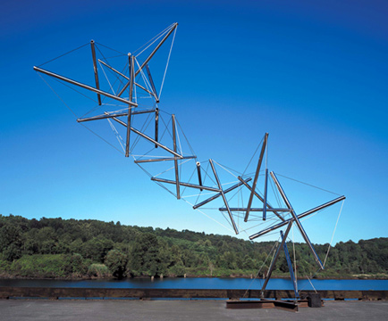
I just remembered – On one of the trips I did when I was working overseas, we had enough time one day when we were at Washington, near the Smithsonian museum. This photo was the first time I’d ever seen a sculpture like that, it blew me away how clever it was.
Spiny Norman said:
I just remembered – On one of the trips I did when I was working overseas, we had enough time one day when we were at Washington, near the Smithsonian museum. This photo was the first time I’d ever seen a sculpture like that, it blew me away how clever it was.
Wow, nice. I wouldn’t have expected that was possible.
You can get a truss like that I drew above by turning an arch bridge sideways. Left diagram below.
The compression elements remain compression elements and the tension elements remain tension elements.
mollwollfumble said:
Spiny Norman said:
I just remembered – On one of the trips I did when I was working overseas, we had enough time one day when we were at Washington, near the Smithsonian museum. This photo was the first time I’d ever seen a sculpture like that, it blew me away how clever it was.Wow, nice. I wouldn’t have expected that was possible.
You can get a truss like that I drew above by turning an arch bridge sideways. Left diagram below.
The compression elements remain compression elements and the tension elements remain tension elements.
It just occurred to me that the curve of a cable of a suspension bridge such as the Golden Gate should be a parabola, not a catenary, because the weight of the bridge deck far exceeds the weight of the cable. For the compression truss above, the correct ideal shape for the curve is a parabola. If the maximum deflection is delta at midspan L/2, then the angle from vertical to truss at top is arctan(delta/4L).
I guess you know what Robert Hooke had to say on the optimum shape for an arch:
“abcccddeeeeefggiiiiiiiillmmmmnnnnnooprrsssttttttuuuuuuuvx”
But I’m not convinced that the optimum shape for your truss is either a parabola or a catenary, since the deflected shape would be a cubic if the truss had constant flexural stiffness, or some higher order curve if the shape gets stiffer towards mid-span.
Also if you want to do some frame analysis you could try:
The Rev Dodgson said:
“abcccddeeeeefggiiiiiiiillmmmmnnnnnooprrsssttttttuuuuuuuvx”
It is impossible for a cube to be the sum of two cubes, a fourth power to be the sum of two fourth powers, or in general for any number that is a power greater than the second to be the sum of two like powers. I have discovered a truly marvelous demonstration of this proposition that this margin is too narrow to contain.
these always seem like such cop out moves though
SCIENCE said:
The Rev Dodgson said:“abcccddeeeeefggiiiiiiiillmmmmnnnnnooprrsssttttttuuuuuuuvx”It is impossible for a cube to be the sum of two cubes, a fourth power to be the sum of two fourth powers, or in general for any number that is a power greater than the second to be the sum of two like powers. I have discovered a truly marvelous demonstration of this proposition that this margin is too narrow to contain.
these always seem like such cop out moves though
That certainly sounds like Hooke, but it’s not the translation of the quote.
The Rev Dodgson said:
I guess you know what Robert Hooke had to say on the optimum shape for an arch:“abcccddeeeeefggiiiiiiiillmmmmnnnnnooprrsssttttttuuuuuuuvx”
But I’m not convinced that the optimum shape for your truss is either a parabola or a catenary, since the deflected shape would be a cubic if the truss had constant flexural stiffness, or some higher order curve if the shape gets stiffer towards mid-span.
Hooke?
Truss is a parabola if the flexural stiffness of the individual compression members is very small relative to the overall moment of inertia of the truss, and it is in this case.
From flexural stiffness of individual compression members alone, the shape would be sinusoidal rather than either parabolic or catenary.
I’m old enough that “that looks about right” often governs my engineering. Well, what I’m ending up with here doesn’t look even rmotely right. Can you imagine a load of 1.654 kN ultimate load being carried over a length of 86 metres by a few elements with a wall thickness of 0.0381 mm? Impossible? Of course. But the calculations say it isn’t.
Start with single tube of mild steel. Perfect manufacturing, zero error tolerance.
Calcs using three equations for three failure modes. ie. direct compression (UTS = 400 MPa), Euler buckling, and thin wall buckling.
Tube wall thickness 0.0660 mm
Tube radius 10 mm
Length 0.495 m
Fails by all three methods at a compressive load of 1.654 kN.
Now change that to a truss. Again perfect manufacturing, braced to bend in Euler bucking as a single unit.
3 tubes of mild steel, bent into parabolic shape.
Tube wall thickness 0.0381 mm
Tube radius 5.7735 mm
Distance between tube centreline and truss centreline at mid-span 1 m
Truss length 86 m
Fails by all three methods at a compressive load of 1.654 kN.
Hell that’s lightweight !!
Seems impossible. But unless I’m missing my guess in saying that the moment of inertia of this truss cross section can be obtained in the normal way (parallel axis theorem) then it’s actually possible (deliberately ignoring non-linear interactions between the three failure modes).
ie. the weight of a truss compression element can be just a small percentage heavier than the weight of a tension element.
mollwollfumble said:
The Rev Dodgson said:
I guess you know what Robert Hooke had to say on the optimum shape for an arch:“abcccddeeeeefggiiiiiiiillmmmmnnnnnooprrsssttttttuuuuuuuvx”
But I’m not convinced that the optimum shape for your truss is either a parabola or a catenary, since the deflected shape would be a cubic if the truss had constant flexural stiffness, or some higher order curve if the shape gets stiffer towards mid-span.
Hooke?
Yes, he wrote:
As hangs the flexible line,
So but inverted stands the rigid arch.
But arch shape and column buckling are two totally different problems.
In the case of an arch (or cable) the offset of the arch from the base in just the right shape balances the moments due to transverse load with an equal and opposite moment due to the reaction at the base, so in principle if the arch was just the right shape it would stand even if it had zero flexural stiffness (and a cable is stable even though it actually does have negligible flexural stiffness).
For a column there is no transverse load, and the moment due to the load eccentricity is balanced by the flexural stiffness of the section, so if you reduce the stiffness along the length the deflection increases and the buckling load decreases.
I have run your two examples in my buckling spreadsheet that allows the column to be divided into segments with different stiffness. I ran the analysis as a cantilever column with fixed base and free top, so effectively half of your pinned top and bottom.
For a single tube with constant cross section I agree exactly with your calculation (after I got my units right).
For a three tube truss, with a constant radius of 1 metre , I get a length of 24.8 m for the 1.65 kN buckling load (so pinned/pinned length = 49.6m).
If I reduce the radius from 1 metre at the base to 0.1 metre at the top, along a parabolic curve, the buckling load reduces to 1.5 mN, so a reduction in capacity of about 1 million.
See Buckling of column with varying cross section for spreadsheet download.
The Rev Dodgson said:
mollwollfumble said:
The Rev Dodgson said:
I guess you know what Robert Hooke had to say on the optimum shape for an arch:“abcccddeeeeefggiiiiiiiillmmmmnnnnnooprrsssttttttuuuuuuuvx”
But I’m not convinced that the optimum shape for your truss is either a parabola or a catenary, since the deflected shape would be a cubic if the truss had constant flexural stiffness, or some higher order curve if the shape gets stiffer towards mid-span.
Hooke?
Yes, he wrote:
As hangs the flexible line,
So but inverted stands the rigid arch.But arch shape and column buckling are two totally different problems.
In the case of an arch (or cable) the offset of the arch from the base in just the right shape balances the moments due to transverse load with an equal and opposite moment due to the reaction at the base, so in principle if the arch was just the right shape it would stand even if it had zero flexural stiffness (and a cable is stable even though it actually does have negligible flexural stiffness).
For a column there is no transverse load, and the moment due to the load eccentricity is balanced by the flexural stiffness of the section, so if you reduce the stiffness along the length the deflection increases and the buckling load decreases.
I have run your two examples in my buckling spreadsheet that allows the column to be divided into segments with different stiffness. I ran the analysis as a cantilever column with fixed base and free top, so effectively half of your pinned top and bottom.
For a single tube with constant cross section I agree exactly with your calculation (after I got my units right).
For a three tube truss, with a constant radius of 1 metre , I get a length of 24.8 m for the 1.65 kN buckling load (so pinned/pinned length = 49.6m).
If I reduce the radius from 1 metre at the base to 0.1 metre at the top, along a parabolic curve, the buckling load reduces to 1.5 mN, so a reduction in capacity of about 1 million.
See Buckling of column with varying cross section for spreadsheet download.
I really should check my numbers when getting ridiculous looking results.
Using the correct stiffness calculation the buckling load of the parabolic tapered truss reduces to 1.12 kN, so a reduction of about 32%.
So not quite 1 million times less, but still a significant reduction.
The Rev Dodgson said:
The Rev Dodgson said:
mollwollfumble said:Hooke?
Yes, he wrote:
As hangs the flexible line,
So but inverted stands the rigid arch.But arch shape and column buckling are two totally different problems.
In the case of an arch (or cable) the offset of the arch from the base in just the right shape balances the moments due to transverse load with an equal and opposite moment due to the reaction at the base, so in principle if the arch was just the right shape it would stand even if it had zero flexural stiffness (and a cable is stable even though it actually does have negligible flexural stiffness).
For a column there is no transverse load, and the moment due to the load eccentricity is balanced by the flexural stiffness of the section, so if you reduce the stiffness along the length the deflection increases and the buckling load decreases.
I have run your two examples in my buckling spreadsheet that allows the column to be divided into segments with different stiffness. I ran the analysis as a cantilever column with fixed base and free top, so effectively half of your pinned top and bottom.
For a single tube with constant cross section I agree exactly with your calculation (after I got my units right).
For a three tube truss, with a constant radius of 1 metre , I get a length of 24.8 m for the 1.65 kN buckling load (so pinned/pinned length = 49.6m).
If I reduce the radius from 1 metre at the base to 0.1 metre at the top, along a parabolic curve, the buckling load reduces to 1.5 mN, so a reduction in capacity of about 1 million.
See Buckling of column with varying cross section for spreadsheet download.
Bump for moll:
I really should check my numbers when getting ridiculous looking results.
Using the correct stiffness calculation the buckling load of the parabolic tapered truss reduces to 1.12 kN, so a reduction of about 32%.
So not quite 1 million times less, but still a significant reduction.
> See Buckling of column with varying cross section for spreadsheet download.
Ta. Will do. Just what I need.
The ideal tuss half-angle at the support for mild steel turns out to be 2.66 degrees.
This gives a volume independent (and thickness independent, to first order) universal shape for an ideal compression truss over arbitrary length.
Given changing length and load, the overall shape of the truss doesn’t change, the ratio of tube wall thickness to tube radius doesn’t change, but the actual tube wall thickness and tube radius increases as the load increases.
A single compression element consisting of six tubes (of mild steel) spot glued together in a circle gives a 58% longer buckling length than a single tube of the same total cross sectional area.
Still to determine – weight of stringers and other elemets needed to prevent buckling. That will tell me (I hope) how many tubes to carry the compression is optimal.
Catenary – curve for tension + self weight, eg. high voltage cable.
Parabola – curve for tension + uniformly distributed load, eg. suspension bridge, the deck is a UDL
Parabola – curve for compression + UCL, eg. arch bridge.
Sine – curve for compression + flex, eg. Euler buckling.
I don’t want to know what curve is needed for a combination of tension, self-weight, UHL, flex and prestress. Just stuck to the above.
The Rev Dodgson said:
mollwollfumble said:
Question for Rev D.I have a pin-ended long compression member.
What’s the ideal truss shape?
I’d thought you’d done your own research on that :)
I don’t do steel design, so I don’t really know, but if “ideal” means minimum cost for a given load, using readily available materials, I’d guess a triangular cross section.
Triangular it is. Well done.
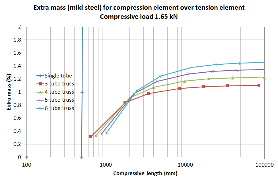
The extra masses for the trusses in the following chart come from three sources: the horizontal stringers, the stiffening of the vertical tubes to avoid wall buckling where the stringers join the tubes, and the thickening of the tube walls needed to compensate for the non-verticality of the tubes.
The important thing to note here from the chart is that the extra mass for a compression element over that required a tension element of the same length is small, only about 1% more than for a tension element for arbitrary length. This was, shall we say, totally unexpected, and relies on three assumptions that are probably unrealistic:
mollwollfumble said:
> See Buckling of column with varying cross section for spreadsheet download.Ta. Will do. Just what I need.
The ideal tuss half-angle at the support for mild steel turns out to be 2.66 degrees.
This gives a volume independent (and thickness independent, to first order) universal shape for an ideal compression truss over arbitrary length.
Given changing length and load, the overall shape of the truss doesn’t change, the ratio of tube wall thickness to tube radius doesn’t change, but the actual tube wall thickness and tube radius increases as the load increases.A single compression element consisting of six tubes (of mild steel) spot glued together in a circle gives a 58% longer buckling length than a single tube of the same total cross sectional area.
Still to determine – weight of stringers and other elemets needed to prevent buckling. That will tell me (I hope) how many tubes to carry the compression is optimal.
Catenary – curve for tension + self weight, eg. high voltage cable.
Parabola – curve for tension + uniformly distributed load, eg. suspension bridge, the deck is a UDL
Parabola – curve for compression + UCL, eg. arch bridge.
Sine – curve for compression + flex, eg. Euler buckling.
I don’t want to know what curve is needed for a combination of tension, self-weight, UHL, flex and prestress. Just stuck to the above.
Where did the 2.66 degrees and sine curve come from?
Any reduction in the I (2nd moment of area) along the length of the truss will increase the deflection and reduce the buckling load.
Did you see this before?
Elegant solutions, Column buckling, and the hole through the middle of the Earth
The Rev Dodgson said:
Where did the 2.66 degrees and sine curve come from?Any reduction in the I (2nd moment of area) along the length of the truss will increase the deflection and reduce the buckling load.
Did you see this before?
Elegant solutions, Column buckling, and the hole through the middle of the Earth
The sine curve is the solution of classical Euler buckling. eg. the last line in the wikipedia section https://en.wikipedia.org/wiki/Euler%27s_critical_load#Pin_ended_column
The 2.66 degrees turned out to be a little bit off. The number takes a fair bit of calculation, equating the failure load for different failure mechanisms. It’s the truss end half-angle, the slope of the parabola at thge end points. As the total length of the compression element increases towards about 100 metres long.
3 tube truss – 2.64 degrees
4 tube truss – 2.29 degrees
6 tube truss – 1.87 degrees
ie. these trusses are very slender compared to what you’s see for example on a shear leg for a crane.
> Any reduction in the I (2nd moment of area) along the length of the truss will increase the deflection and reduce the buckling load.
Yep, that’s why I increase the I along the length of the truss to decrease the deflection and increase the buckling load.
> Did you see this before?
Not yet, thanks. Will look at soon.
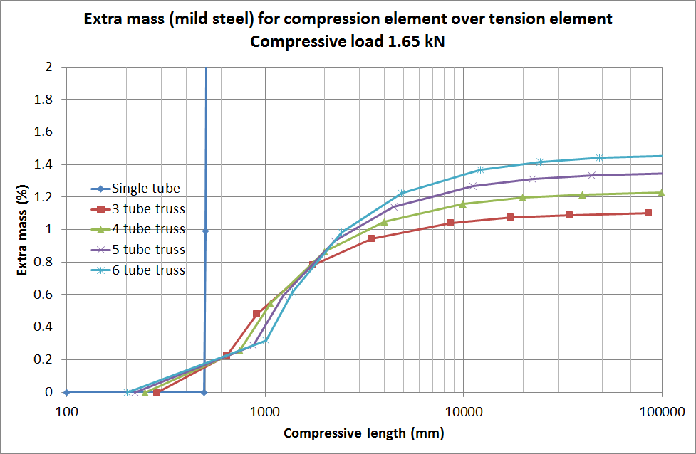
I’ve refined the above graph a little. This is a little better, less extra mass at smaller truss length.
mollwollfumble said:
Yep, that’s why I increase the I along the length of the truss to decrease the deflection and increase the buckling load.
If you keep the maximum I along the full length it will have a smaller deflection and a higher buckling load than one where the I is reduced towards the two ends, for negligible increase in materials.
How are you fixing the wall thickness of the cylindrical struts?
They seem very thin to me, and the Internet doesn’t seem to have a consensus on how to do it.
First hit from a binge:
https://digital.library.adelaide.edu.au/dspace/bitstream/2440/110253/1/02whole.pdf
The Rev Dodgson said:
How are you fixing the wall thickness of the cylindrical struts?They seem very thin to me, and the Internet doesn’t seem to have a consensus on how to do it.
First hit from a binge:
https://digital.library.adelaide.edu.au/dspace/bitstream/2440/110253/1/02whole.pdf
Bingo. Yes. :-)
That’s exactly the paper I’m getting my cylindrical thin wall buckling from!
I’m using Equation 1.2.1 plus buckling stress reduced by a factor of 2.
The factor of 2 from: “the ratio of the experimental buckling stress to the calculated stress from equation (1.2.1) was approximately one half to two thirds.”
I’ve now bookmarked:
3DFrame
Buckling of column with varying cross section
Elegant solutions, Column buckling, and the hole through the middle of the Earth
and will get to them shortly.
mollwollfumble said:
The Rev Dodgson said:
How are you fixing the wall thickness of the cylindrical struts?They seem very thin to me, and the Internet doesn’t seem to have a consensus on how to do it.
First hit from a binge:
https://digital.library.adelaide.edu.au/dspace/bitstream/2440/110253/1/02whole.pdf
Bingo. Yes. :-)
That’s exactly the paper I’m getting my cylindrical thin wall buckling from!I’m using Equation 1.2.1 plus buckling stress reduced by a factor of 2.
The factor of 2 from: “the ratio of the experimental buckling stress to the calculated stress from equation (1.2.1) was approximately one half to two thirds.”I’ve now bookmarked:
3DFrame
Buckling of column with varying cross section
Elegant solutions, Column buckling, and the hole through the middle of the Earth
and will get to them shortly.
I’m having trouble running 3DFrame. Please try it with the following data. Supported at vertex 1 and 35.
Units are mm, N and MPa (or any other consistent units). Poisson’s ratio nu is included but not needed.
Material,,,
sigma,E,nu,
400,200000,0.303,
,,,
Xsection,A,Ixx,Iyy
1,1.379721354,22.84403,22.84403
2,0.012209958,0.001789033,0.001789033
,,,
Load,,,
Vertex,x,y,z
1,0,0,-1653
35,0,0,1653
,,,
Vertices,x,y,z
1,0,0,2000
2,7.027777778,0,1833.333333
3,-3.513888889,6.086234088,1833.333333
4,-3.513888889,-6.086234088,1833.333333
5,12.77777778,0,1666.666667
6,-6.388888889,11.06588016,1666.666667
7,-6.388888889,-11.06588016,1666.666667
8,17.25,0,1500
9,-8.625,14.93893822,1500
10,-8.625,-14.93893822,1500
11,20.44444444,0,1333.333333
12,-10.22222222,17.70540826,1333.333333
13,-10.22222222,-17.70540826,1333.333333
14,22.36111111,0,1166.666667
15,-11.18055556,19.36529028,1166.666667
16,-11.18055556,-19.36529028,1166.666667
17,23,0,1000
18,-11.5,19.91858429,1000
19,-11.5,-19.91858429,1000
20,22.36111111,0,833.3333333
21,-11.18055556,19.36529028,833.3333333
22,-11.18055556,-19.36529028,833.3333333
23,20.44444444,0,666.6666667
24,-10.22222222,17.70540826,666.6666667
25,-10.22222222,-17.70540826,666.6666667
26,17.25,0,500
27,-8.625,14.93893822,500
28,-8.625,-14.93893822,500
29,12.77777778,0,333.3333333
30,-6.388888889,11.06588016,333.3333333
31,-6.388888889,-11.06588016,333.3333333
32,7.027777778,0,166.6666667
33,-3.513888889,6.086234088,166.6666667
34,-3.513888889,-6.086234088,166.6666667
35,0,0,0
,,,
Elements,,,
number,vertex1,vertex2,Xsection
1,1,2,1
2,1,3,1
3,1,4,1
4,2,5,1
5,3,6,1
6,4,7,1
7,5,8,1
8,6,9,1
9,7,10,1
10,8,11,1
11,9,12,1
12,10,13,1
13,11,14,1
14,12,15,1
15,13,16,1
16,14,17,1
17,15,18,1
18,16,19,1
19,17,20,1
20,18,21,1
21,19,22,1
22,20,23,1
23,21,24,1
24,22,25,1
25,23,26,1
26,24,27,1
27,25,28,1
28,26,29,1
29,27,30,1
30,28,31,1
31,29,32,1
32,30,33,1
33,31,34,1
34,32,35,1
35,33,35,1
36,34,35,1
37,2,3,2
38,3,4,2
39,4,2,2
40,5,6,2
41,6,7,2
42,7,5,2
43,8,9,2
44,9,10,2
45,10,8,2
46,11,12,2
47,12,13,2
48,13,11,2
49,14,15,2
50,15,16,2
51,16,14,2
52,17,18,2
53,18,19,2
54,19,17,2
55,20,21,2
56,21,22,2
57,22,20,2
58,23,24,2
59,24,25,2
60,25,23,2
61,26,27,2
62,27,28,2
63,28,26,2
64,29,30,2
65,30,31,2
66,31,29,2
67,32,33,2
68,33,34,2
69,34,32,2
mollwollfumble said:
mollwollfumble said:
The Rev Dodgson said:
How are you fixing the wall thickness of the cylindrical struts?They seem very thin to me, and the Internet doesn’t seem to have a consensus on how to do it.
First hit from a binge:
https://digital.library.adelaide.edu.au/dspace/bitstream/2440/110253/1/02whole.pdf
Bingo. Yes. :-)
That’s exactly the paper I’m getting my cylindrical thin wall buckling from!I’m using Equation 1.2.1 plus buckling stress reduced by a factor of 2.
The factor of 2 from: “the ratio of the experimental buckling stress to the calculated stress from equation (1.2.1) was approximately one half to two thirds.”I’ve now bookmarked:
3DFrame
Buckling of column with varying cross section
Elegant solutions, Column buckling, and the hole through the middle of the Earth
and will get to them shortly.
I’m having trouble running 3DFrame. Please try it with the following data. Supported at vertex 1 and 35.
Units are mm, N and MPa (or any other consistent units). Poisson’s ratio nu is included but not needed.Material,,,
sigma,E,nu,
400,200000,0.303,
,,,
Xsection,A,Ixx,Iyy
1,1.379721354,22.84403,22.84403
2,0.012209958,0.001789033,0.001789033
,,,
Load,,,
Vertex,x,y,z
1,0,0,-1653
35,0,0,1653
,,,
Vertices,x,y,z
1,0,0,2000
2,7.027777778,0,1833.333333
3,-3.513888889,6.086234088,1833.333333
4,-3.513888889,-6.086234088,1833.333333
5,12.77777778,0,1666.666667
6,-6.388888889,11.06588016,1666.666667
7,-6.388888889,-11.06588016,1666.666667
8,17.25,0,1500
9,-8.625,14.93893822,1500
10,-8.625,-14.93893822,1500
11,20.44444444,0,1333.333333
12,-10.22222222,17.70540826,1333.333333
13,-10.22222222,-17.70540826,1333.333333
14,22.36111111,0,1166.666667
15,-11.18055556,19.36529028,1166.666667
16,-11.18055556,-19.36529028,1166.666667
17,23,0,1000
18,-11.5,19.91858429,1000
19,-11.5,-19.91858429,1000
20,22.36111111,0,833.3333333
21,-11.18055556,19.36529028,833.3333333
22,-11.18055556,-19.36529028,833.3333333
23,20.44444444,0,666.6666667
24,-10.22222222,17.70540826,666.6666667
25,-10.22222222,-17.70540826,666.6666667
26,17.25,0,500
27,-8.625,14.93893822,500
28,-8.625,-14.93893822,500
29,12.77777778,0,333.3333333
30,-6.388888889,11.06588016,333.3333333
31,-6.388888889,-11.06588016,333.3333333
32,7.027777778,0,166.6666667
33,-3.513888889,6.086234088,166.6666667
34,-3.513888889,-6.086234088,166.6666667
35,0,0,0
,,,
Elements,,,
number,vertex1,vertex2,Xsection
1,1,2,1
2,1,3,1
3,1,4,1
4,2,5,1
5,3,6,1
6,4,7,1
7,5,8,1
8,6,9,1
9,7,10,1
10,8,11,1
11,9,12,1
12,10,13,1
13,11,14,1
14,12,15,1
15,13,16,1
16,14,17,1
17,15,18,1
18,16,19,1
19,17,20,1
20,18,21,1
21,19,22,1
22,20,23,1
23,21,24,1
24,22,25,1
25,23,26,1
26,24,27,1
27,25,28,1
28,26,29,1
29,27,30,1
30,28,31,1
31,29,32,1
32,30,33,1
33,31,34,1
34,32,35,1
35,33,35,1
36,34,35,1
37,2,3,2
38,3,4,2
39,4,2,2
40,5,6,2
41,6,7,2
42,7,5,2
43,8,9,2
44,9,10,2
45,10,8,2
46,11,12,2
47,12,13,2
48,13,11,2
49,14,15,2
50,15,16,2
51,16,14,2
52,17,18,2
53,18,19,2
54,19,17,2
55,20,21,2
56,21,22,2
57,22,20,2
58,23,24,2
59,24,25,2
60,25,23,2
61,26,27,2
62,27,28,2
63,28,26,2
64,29,30,2
65,30,31,2
66,31,29,2
67,32,33,2
68,33,34,2
69,34,32,2
Won’t have time before the weekend.
If you could send your file to my gmail address which is dougaj4 it will save me some time.
The Rev Dodgson said:
Won’t have time before the weekend.
If you could send your file to my gmail address which is dougaj4 it will save me some time.
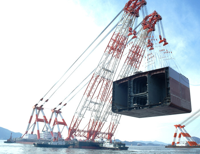
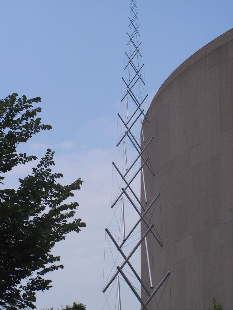
The overall truss shape I’m coming up with somewhat resembles this truss from wikimedia commons. Very slender, pointed ends, increase and decrease in width roughly parabolic in shape. A difference here is that the following truss also has to be rigid under self-weight.
And this one from liftech consultants.
mollwollfumble said:
The Rev Dodgson said:Won’t have time before the weekend.
If you could send your file to my gmail address which is dougaj4 it will save me some time.The overall truss shape I’m coming up with somewhat resembles this truss from wikimedia commons. Very slender, pointed ends, increase and decrease in width roughly parabolic in shape. A difference here is that the following truss also has to be rigid under self-weight.
And this one from liftech consultants.
Note that the real heavy lift truss has parallel sides over most of it’s length, rather than a curved profile, and this increases the buckling load for negligible increase in steel volume.
Also note that the bracing elements have a longitudinal slope , rather than being in the transverse plane, and I would expect that to increase the buckling load too.
I actually did some work on your truss thu/fri. I’ll tidy things up and post something later.
Didn’t receive anything at gmail.