Some help if I may. Others can put their two bobs worth in as well.
Have I cooked my silly scope somehow?
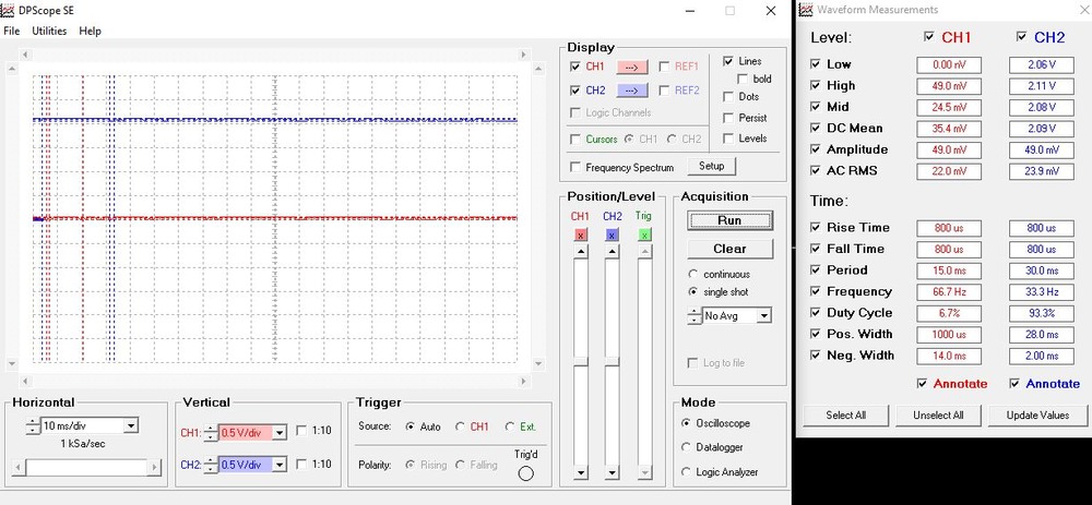
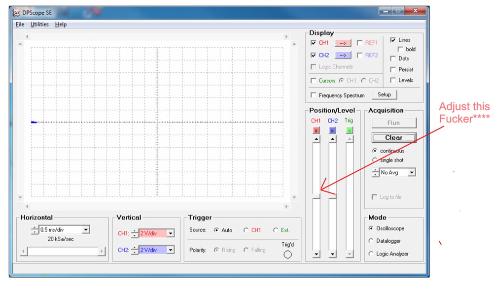
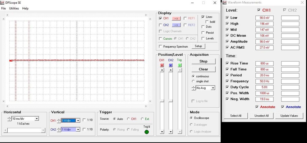
It did work, if you remember. But on plugging it in this time, I get a constant ~ 2.2V on each channel. No probes connected. Note the amplitude.~0.
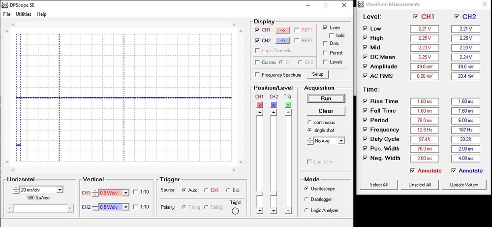
Dunno why.
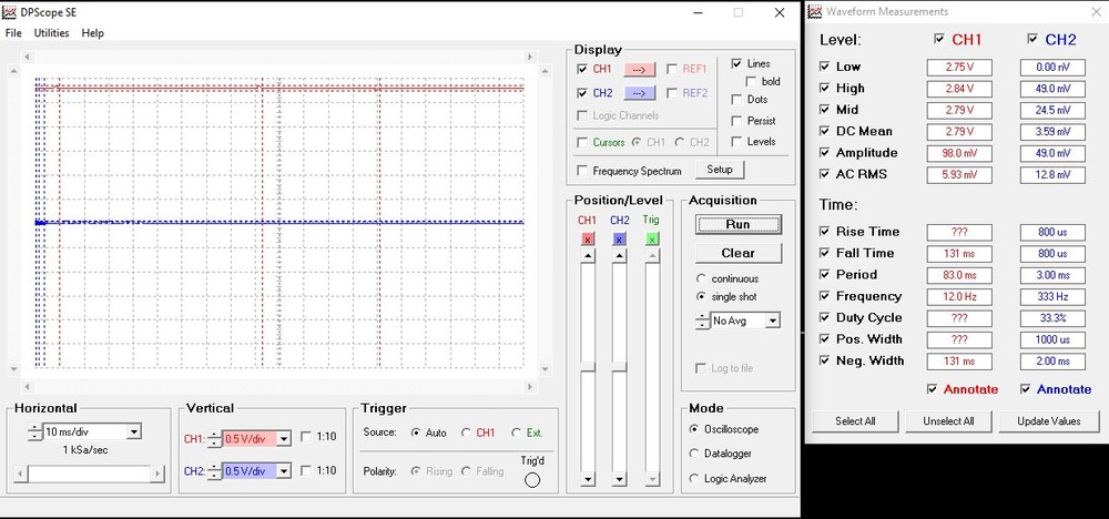
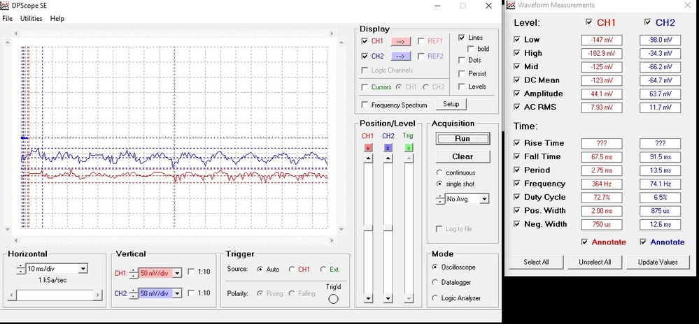
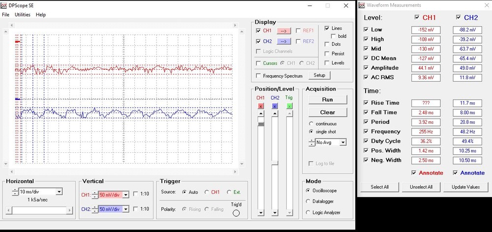
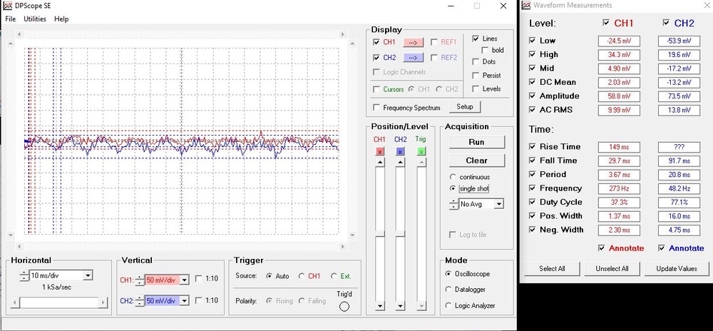
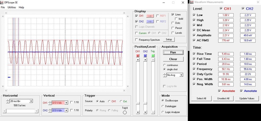
Next, If I touch (finger) a channel pin/probe I get a 50hz oscillation with an amplitude of ~ 2.2V Get the same if I touch the channel 2 pin as well.
Finger on channel 1 probe/pin only.
I have tried a range of laptops and desktop. Changed the USB cable and ports. No diff
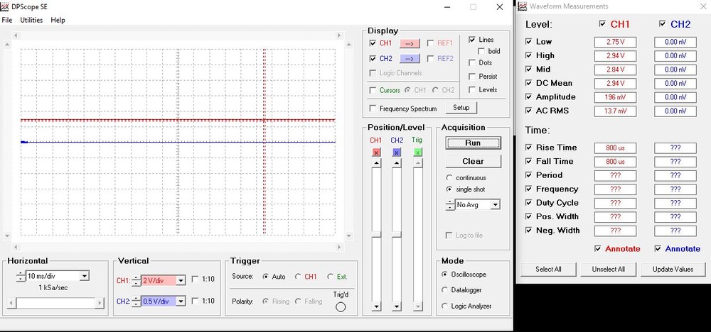
NB: On laptops, I **don’t ** get the 50hz oscillation if I unplug the power supply and run on battery when touching the channel pin. But still get the ~ 2.2V reading on both channels.
Next: I had soldered a new row of pins onto the board of the original, to mount it in a box with BNC plugs for proper probes..
Next. So I went and got another one, thinking I’d cooked the original one.. https://www.wiltronics.com.au/product/8564/picpcb-scope-oscilloscope/
Circuit diagram here https://picaxe.com/docs/osc001_schematic.pdf
But nup. The new one does the same thing. On both channels. I didn’t test it BEFORE soldering the pins on. Carefully and minimally soldered the pins on.
The thing is powered via the USB port, and the scope software has a utility to check the USB power supply voltage of the USB port. This checks out OK and is within correct range of 4.5 – 5.5 V.
I can’t believe I’ve cooked TWO of them the same way, on BOTH channels.
This time, I’m trying to detect “noise” in the phase shift/voltage spikes of the 14V AC power supply to the track of the toots. Noise that can be caused by arcing of the motor brushes in the loco, or very tiny shorts caused by train wheels crossing track points.
I’m stumped. Other than get ANOTHER one, and test it BEFORE I solder the pins on.
I did connect it to a 9V battery, and got silly erratic readings, and if I hold the battery case, it goes berserk.
Any ideas?
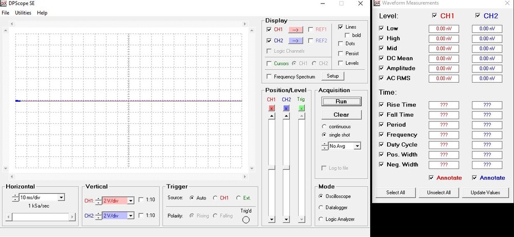
With nothing connected, I should get a 0V reading on both channels?
wadda ya reckon, hey what but.